Product Description
Right Angle Vertical Output Reducer Speed Gearbox
Product Description
Technical data:
1. Power: 0.37-200 (KW)
2. Output Speed: 11-226RMP,
3. Torque: 400-56000 (N. M)
4. Transmission stage: Three stage
Applications:
The products are widely applied in electricity, coal, cement, metallurgy, harbor, agriculture, shipping, lifting, environment protection, stage, logistic, weaving, paper making, light industry, plastics and other regions
1. We accept sample order.
2. We undertake the problems due to quality.
3. We supply detail answers about technical questions.
4. We are the manufacturer so we could supply the products as soon as possible.
5. At the instance of our dear customer, we can do the customized gear boxes for clients.
Detailed Photos
Commercial information:
1. MOQ: 1 set
2. Packing method: Polywood
3. Delivery lead time: 10-25 days
4. Price terms: FOB, CIF, EXW
5. Payment method: T/T, 30% in advance, 70% balance before delivery
6. Shipping port: HangZhou
7. OEM: We accept customized products as per your special requirement.
8. Xihu (West Lake) Dis.lines for the Selection: Usually we can select 1 machine which is suitable for you with some informations from you, such as ratio/motor speed/mounting dimension/ output torque etc.
9. If the minimum order amount is in excess of $10000, there are preferential
| input power | 0.018-96kw |
| ratio | 1-3 |
| permissable torque | 11-607N.M |
| mounting type: | footmounted |
| usage: | change direction |
Product Parameters
| Models | Input Power | Ratio | Max. Torque | Weight(kg) | Output Shaft Dia.(k6) |
| T2 | 0.014KW~1.79KW | 1~2 | 11 | 2 | Φ15 |
| T4 | 0.026KW~4.94KW | 1~2 | 31 | 10 | Φ19 |
| T6 | 0.037KW~14.9KW | 1~3 | 94 | 21 | Φ25 |
| T7 | 0.042KW~22KW | 1~3 | 139 | 32 | Φ32 |
| T8 | 0.064KW~45.6KW | 1~3 | 199 | 49 | Φ40 |
| T10 | 0.11KW~65.3KW | 1~3 | 288 | 78 | Φ45 |
| T12 | 0.188KW~96KW | 1~3 | 607 | 124 | Φ50 |
| T16 | 0.40KW~163KW | 1~3 | 1073 | 188 | Φ60 |
| T20 | 0.69KW~234KW | 1~3 | 1943 | 297 | Φ72 |
| T25 | 1.4KW~335KW | 1~3 | 3677 | 488 | Φ85 |
Ratio: 1:1, 1.5:1, 2:1, 2.5:1, 3:1
Packaging & Shipping
Company Profile
After Sales Service
| Pre-sale services | 1. Select equipment model. |
| 2.Design and manufacture products according to clients’ special requirement. | |
| 3.Train technical personal for clients | |
| Services during selling | 1.Pre-check and accept products ahead of delivery. |
| 2. Help clients to draft solving plans. | |
| After-sale services | 1.Assist clients to prepare for the first construction scheme. |
| 2. Train the first-line operators. | |
| 3.Take initiative to eliminate the trouble rapidly. | |
| 4. Provide technical exchanging. |
FAQ
FAQ:
1.Q:What kinds of gearbox can you produce for us?
A:Main products of our company: UDL series speed variator,RV series worm gear reducer, ATA series shaft mounted gearbox, X,B series gear reducer,
P series planetary gearbox and R, S, K, and F series helical-tooth reducer, more
than 1 hundred models and thousands of specifications
2.Q:Can you make as per custom drawing?
A: Yes, we offer customized service for customers.
3.Q:What is your terms of payment ?
A: 30% Advance payment by T/T after signing the contract.70% before delivery
4.Q:What is your MOQ?
A: 1 Set
Welcome to contact us for more detail information and inquiry.
If you have specific parameters and requirement for our gearbox, customization is available.
| Application: | Machinery, Industry |
|---|---|
| Function: | Change Drive Direction, Speed Reduction |
| Layout: | Right Angle |
| Hardness: | Hardened |
| Installation: | Vertical Type |
| Step: | Single-Step |
| Samples: |
US$ 1/Piece
1 Piece(Min.Order) | |
|---|
| Customization: |
Available
| Customized Request |
|---|
How do you ensure proper alignment when connecting miter gears?
Proper alignment is crucial when connecting miter gears to ensure smooth and efficient power transmission. Here are some key steps to ensure proper alignment:
- Shaft Alignment: Start by ensuring that the shafts on which the miter gears are mounted are properly aligned. Misalignment of the shafts can lead to increased friction, premature wear, and reduced efficiency. Use alignment tools such as dial indicators or laser alignment systems to accurately align the shafts.
- Gear Positioning: Position the miter gears in such a way that their axes intersect at a 90-degree angle. This ensures proper meshing of the gears and optimal power transmission. Pay attention to the position of the gears and make any necessary adjustments to achieve the desired alignment.
- Bearing Support: Proper bearing support is essential for maintaining alignment and reducing excessive loading on the gears. Ensure that the bearings supporting the shafts are accurately installed and aligned. Use high-quality bearings suitable for the load and speed requirements of the miter gears.
- Clearance and Backlash: Check for proper clearance and backlash between the teeth of the miter gears. Clearance refers to the space between the mating teeth, while backlash is the amount of play or movement between the gears. Proper clearance and backlash allow for smooth engagement and disengagement of the gears without binding or excessive noise.
- Lubrication: Apply a suitable lubricant to the miter gears to reduce friction and wear. Proper lubrication ensures smooth operation and helps maintain alignment by minimizing heat buildup and preventing excessive wear on the gear teeth.
By following these steps, you can ensure proper alignment when connecting miter gears, resulting in efficient power transmission, reduced wear, and improved overall performance.

How do you calculate the gear ratio in a miter gear assembly?
The gear ratio in a miter gear assembly can be calculated by considering the number of teeth on the gears involved. Here’s a step-by-step explanation:
1. Determine the Number of Teeth:
Identify the number of teeth on both the driving gear (input gear) and the driven gear (output gear) in the miter gear assembly. The number of teeth can usually be found in the gear specifications or by physically counting the teeth.
2. Calculate the Gear Ratio:
To calculate the gear ratio, divide the number of teeth on the driven gear (output gear) by the number of teeth on the driving gear (input gear). The formula for calculating the gear ratio is:
Gear Ratio = Number of Teeth on Driven Gear / Number of Teeth on Driving Gear
3. Simplify the Ratio (Optional):
If the resulting gear ratio is a fraction, it can be simplified to its simplest form. Divide both the numerator and the denominator by their greatest common divisor to simplify the ratio.
4. Interpret the Gear Ratio:
The gear ratio indicates the relationship between the rotational speed or angular velocity of the driving gear and the driven gear. It represents how many times the driven gear rotates for each rotation of the driving gear. For example, a gear ratio of 2:1 means that the driven gear rotates twice for every rotation of the driving gear.
5. Consider the Significance:
The gear ratio has practical implications in determining the mechanical advantage and speed reduction/amplification in a miter gear assembly. A gear ratio greater than 1 indicates a speed reduction and increased torque, while a gear ratio less than 1 indicates a speed amplification and decreased torque.
In summary, the gear ratio in a miter gear assembly is calculated by dividing the number of teeth on the driven gear by the number of teeth on the driving gear. This ratio represents the relationship between the rotational speeds of the gears and provides insights into the mechanical advantage and speed transformation in the gear assembly.
Can you explain the unique design of miter gear teeth?
The design of miter gear teeth is distinct and plays a crucial role in the functionality of these gears. Here’s a detailed explanation:
1. Tooth Shape:
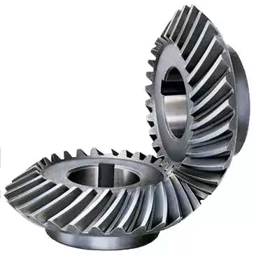
Miter gear teeth have a straight shape, similar to spur gears. However, unlike spur gears where the teeth are parallel to the gear axis, miter gear teeth are cut at a right angle to the gear’s face. This allows the teeth to engage correctly when two miter gears mesh together at a 90-degree angle.
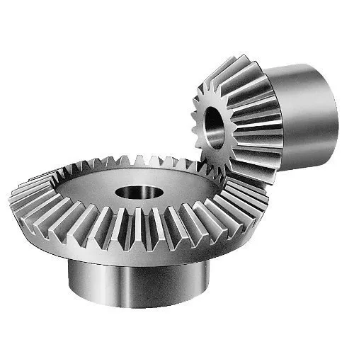
2. Equal Number of Teeth:
Miter gears have an equal number of teeth on both gears in a pair. This ensures proper meshing and smooth transmission of rotational motion between the gears. The equal number of teeth is essential for maintaining a constant speed ratio and preventing any slippage or irregular motion.
3. Conical Shape:
Another unique aspect of miter gear teeth is the conical shape of the gears themselves. The teeth are cut on the conical surface, which allows for proper engagement and transmission of motion between intersecting shafts. The conical shape ensures that the teeth mesh correctly, providing efficient power transmission at the desired angle.
4. Meshing at 90-Degree Angle:
Miter gears are designed to mesh at a 90-degree angle, allowing for power transmission between intersecting shafts. The teeth are specifically cut to facilitate this arrangement, ensuring that the gears engage smoothly and transmit rotational motion without any loss or disruption.
5. Tooth Contact and Load Distribution:
When miter gears mesh, the contact between the teeth occurs along a single line, known as the line of contact. This concentrated contact area enables effective load distribution and ensures that the gear teeth bear the transmitted torque evenly. Proper tooth contact is vital for minimizing wear and maintaining the longevity of the gears.
6. Lubrication and Noise Reduction:
The unique design of miter gear teeth can influence lubrication and noise levels. Adequate lubrication is essential to reduce friction and wear between the teeth during operation. Additionally, the straight tooth profile of miter gears tends to produce more noise compared to gears with helical or curved teeth. Proper lubrication and noise reduction measures are often employed to optimize the performance of miter gears.
In summary, the unique design of miter gear teeth includes their straight shape, equal number of teeth, conical shape of the gears, meshing at a 90-degree angle, tooth contact along a line, and considerations for lubrication and noise reduction. These design features ensure efficient power transmission, proper load distribution, and reliable operation in mechanical systems that utilize miter gears.


editor by CX 2023-10-16